-40%
DC 5V-36V Trigger Cycle Timer Delay Relay Switch Circuit Module MOS Tube Housing
$ 3.23
- Description
- Size Guide
Description
HomeArduino
Module
Sensor
Chips
About Us
Description:
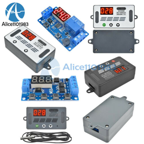
ZK-J06 is a multifunction delay relay module.Digital tube display.It can be widely used at Smart home, Industrial control, Automatic irrigation, Indoor ventilation. And protection equipment.
Features:
1>.Digital tube display
2>.Support high level trigger
3>.Emergency stop function
4>.Sleep mode,Wake up with any button
5>.Automatically save parameters
6>.Dual MOS control support more than 15A 400W
7>.Support reverse connection protection
8>.Continuously adjustable from 0.01 seconds to 9999 minutes
9>.Optocoupler isolation to enhance anti-interference ability
Parameters :
1>.Product Name:ZK-J06 Delay Relay Module
2>.Product Number:ZK-J06
3>.Working Voltage:DC 5V-36V
4>.Control Current:30A(Max and need heat sink!Normal temperature 15A 400W)
5>.Quiescent Current:15mA
6>.Working Current:50mA
7>.Trigger signal source: High level trigger (3.0V~24V)
8>.Reverse protection:Yes
9>.Size:60*39*14mm
Work Mode:
P1.1:Output keep ON for time OP after get trigger signal and then OFF;The input signal is invalid if get trigger signal again during delay time OP.
P1.2:Output keep ON for time OP after get trigger signal and then OFF;Output will restart delay if get trigger signal again during delay time OP.
P1.3:Output keep ON for time OP after get trigger signal and then OFF;Output will reset and stop timing if get trigger signal again during delay time OP.
P2:Output keep OFF for time CL after get trigger signal and then output keep ON for time OP and then output will OFF.
P3.1:Output keep ON for time OP after get trigger signal and then output keep OFF for time CL and then loops the above action.Output will reset and stop timing and output OFF if get trigger signal again during loops.The number of cycles (LOP) can be set.
P3.2:Output keep ON for time OP after power on without get trigger signal and then output keep OFF for time CL and then loops the above action.The number of cycles (LOP) can be set.Note:this mode no need input signal.
P4:Signal hold function.Reset delay time and relay keep ON if keep get trigger signal.Output OFF after delay time OP when the signal disappears.Reset delay time when get trigger signal again during timing.
Timing range:
1>.Continuously adjustable from 0.1 seconds to 999 minutes.
2>.Enter the settings interface when short press button ‘STOP’ in the OP / CL parameter modification interface(Flashing) to select timing range.
3>.Pay attention to the position where the decimal point moves when the button is pressed.
4>.Display ‘XXX’ No decimal point, the timing range is 1 second ~ 999 seconds.
5>.Display ‘XX.X’ The decimal point is the penultimate, timing range is 0.1 second to 99.9 seconds.
6>.Display ‘X.X.X’ The decimal point is fully lit, timing range is 1 minute to 999 minutes.
7>.For example, if you want to set the OP to 3.2 seconds, move the decimal point to the penultimate position, Screen will display ‘03.2’
8>.OP and CL parameters are the same in different work mode.
9>.It will display OP(CL,LOP) and corresponding delay time by short press button SET in main display interface(when display 000).
10>.It just display OP and corresponding delay time in P1 mode by short press button SET in main display interface.
Parameter Description:
OP: Delay time for turn On;
CL: Delay time Turn OFF;
LOP: Number of cycles.Range is 1-999tims.’----’ means unlimited loop.
Set Parameter:
Long press:keep press button for more than 3second.
1>.Enter set parameter menu by long press button 'SET'.
2>.Work mode will flash at first when set the working mode.Short press the UP/DOWN button to select working mode P1~P4.
3>.Short press SET button to enter the system parameter settings interface.
4>.In the system parameter setting interface, short press the ‘SET’ button to switch the system parameters to be modified, short/long press the UP/DOWN button to modify value;
5>.Short press button ‘STOP’ to select timing range.
6>.Short press button SET to set next parameter.
7>.Save the parameter settings and exit the settings interface when long press ‘SET’ button after all the parameters are set.
8>.Main interface:Display 000 if no output.
9>.Set interface:Long press SET button enter into set interface.Long press SET button again into main interface after set parameter.
Additional Features:
1>.Auto sleep function: Long press button 'STOP' in the normal running interface to turn on or off auto sleep function.
1.1>C-P:Turn ON auto sleep function.Screen will automatically turns off if there is no operation within five minutes.It can be wake up by any buttons.
1.2>.O-d:Turn OFF auto sleep function.
2>.Enabled/Disabled output by short press button STOP:
2.1>.ON:Enabled output during delay time OP.
2.2>.OFF:Disabled output during delay time OP.Module can not output any signal at this mode.
3>.Common ground:User can connect GND of trigger signal to GND of module by short pads GND-T and GND.But it is not recommended, which will reduce the anti-interference ability of the module.
Application:
1>.Motor
2>.Robot
3>.Smart home
4>.Industrial control
5>.Automatic irrigation
6>.Indoor ventilation
7>.Illumination
8>.Alarm system
Note:
1>.Module can output voltage same to input voltage.
2>.GND and GND- can not connect together otherwise module can not work normally.
3>.Please read use manual and description before use.
Package Listing:
1>.1pcs ZK-J06 Delay Relay Module
2>.6pcs Acrylic shell
3>.4pcs M3*12mm Copper column
4>.4pcs M3*5+6mm Copper column
5>.8pcs M3*6 screw
Payment
Shipping
Refund
Payment
We accept PayPal only.
But we only
Accept
your
Ebay Address
,Please Make sure it's 100% right.
Payment must be received in 5 business days of auction closing.
Please leave note for your special request (e.g. Colors or Size) in PayPal when you pay the order.
Any special request cannot be accepted after 24 hours of payment, because most of orders will be processed instantly and same day dispatched.
Shipping
Fill your shipping info
Refund
All package need to
wait 30 days
(US only n
eed 7-10 days)
,
Please take care it.Less than 30 days,we can't take a refund
.
If the item is defect when you receive it or you are not satisfied with it, please return it within 14 days for a replacement or money back. But the items must be back in factory condition. Please contact us and double check the return address before you return it.
If is item is defective in 12 months, you can return it to us. We will send you a new replacement after receiving the defective item.


